


Safe Probes for High-Voltage Measuring Devices
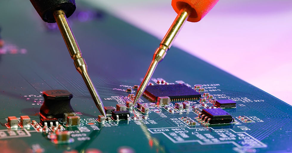
High-voltage (HV) measuring devices translate dangerous electrical potential into usable readings. Engineers use them to evaluate miniature converters, analytical instruments, and compact assemblies.
A safe probe for high-voltage measuring devices serves as the link between the energized circuit and the measuring instrument, so its design influences both operator protection and measurement performance. By reducing voltage through a known divider ratio and incorporating rated insulation, the probe allows the instrument to read hazardous voltages safely.
What Do HV Measuring Devices Measure?
A high-voltage measuring device measures electrical potential above normal low-voltage instrument ranges. In miniature high-voltage products, those readings might involve a regulated direct current output or a bias supply. Other readings may involve a multiplier stage or a pulsed waveform. Each situation changes the stress on the probe because the voltage behavior depends on polarity and frequency.
A meter or oscilloscope alone cannot safely contact many HV nodes. The probe extends the instrument range by scaling the voltage into a readable value. Once the probe reduces the signal, the instrument interprets the output according to the selected ratio.

What Makes a Probe Safe?
A safe probe matches the electrical stress and the physical environment. Voltage rating forms the first limit, while insulation and spacing shape the same safety boundary. Connectors and lead design shape the safe operating boundary.
Safe probes create distance between the user and the energized point. Their housings control creepage across surfaces and clearance through air. Quality designs reduce the chance of arcing or tracking near the probe tip. Engineers should treat the full probe assembly as the safety barrier.
Voltage Rating
Voltage rating tells users the maximum potential the probe can handle within its stated conditions. Engineers often see several voltage specifications on a probe data sheet.
A direct current (DC) rating refers to the maximum continuous direct current voltage the probe can measure safely. It applies to steady outputs, such as regulated HV power supplies and bias circuits.
An alternating current (AC) peak rating refers to the highest instantaneous voltage the probe can withstand during an AC waveform. Since AC voltage rises and falls throughout each cycle, the peak value is higher than the RMS value.
A root-mean-square (RMS) rating describes the effective heating value of an AC waveform. Many electrical systems are specified in RMS voltage because it reflects the amount of power the waveform is able to deliver.
A transient rating describes the probe's ability to withstand short-duration voltage spikes. These spikes may occur during switching events or fault conditions, and they can exceed the normal operating voltage significantly.
A safe selection compares the circuit’s highest possible voltage against the exact rating on the probe data sheet. Engineers should account for switching activity, brief voltage excursions, and compact access around the test point.
Measurement Category
The measurement category defines the expected transient energy. CAT ratings describe the environment around the measurement point, not just the voltage number. CAT I applies to protected electronic circuits. CAT II through CAT IV move closer to branch circuits and distribution panels.
Many HV electronics applications fall outside of power distribution work. Even so, engineers must read the category statement before they trust the voltage rating.
Divider Design
Most HV probes use a precision divider to reduce the voltage before it reaches the meter or oscilloscope. A 1000:1 probe converts 10,000 volts at the tip into 10 volts at the instrument. That reduction protects the instrument input and gives the operator a practical reading.
Divider quality affects safety and data. High-value resistors limit current through the probe, while stable resistor networks preserve the ratio during measurement. Together, these features help maintain consistent readings across the probe's operating range.
Proper internal construction spreads voltage across the assembly instead of concentrating stress at one point. This reduces electrical strain within the probe and supports reliable performance. In HV work, a divider is a controlled electrical structure.
Probe Insulation
The probe body becomes a part of the protection system with insulation. The handle and shaft separate the operator from hazardous voltage. The tip guard and cable support the same safety boundary. With good insulation, surface tracking and internal breakdown are less likely to occur.
Physical design carries extra weight inside compact HV equipment. Test points may sit near shields or housings. Adjacent conductors can sit close to the intended contact point. A long insulated body gives the operator reach while maintaining distance, and a guarded tip limits exposed metal near the contact point.
Single-Ended Probes
Single-ended probes measure the voltage between an energized point and a defined reference. They’re commonly used for DC outputs, bias supplies, and circuits with a known return path. Many probes in this category rely on a divider ratio to scale the voltage before sending it to a voltmeter with a specified input impedance.
Successful measurements depend on proper reference connections. The ground lead should only be attached where the circuit design allows it. In floating or isolated systems, an incorrect reference point can alter circuit operation or create an unintended fault path. For that reason, engineers must verify the return path before using a single-ended probe.
Differential Probes
Unlike single-ended probes, differential probes measure the voltage between two points without using the instrument chassis as the reference. That capability makes them suitable for floating outputs, half-bridge nodes, and switching circuits where significant common-mode voltage is present.
High-voltage differential probes enhance measurement safety through matched inputs and specified common-mode performance. When connected to an oscilloscope, they allow engineers to capture waveform detail while rejecting voltage that appears equally on both inputs.
Meter Compatibility
Probe safety depends on the instrument connected to it. Divider probes assume a specific input impedance at the meter or oscilloscope. A mismatch changes the scale factor and can turn a safe-looking number into a misleading reading.
Compatibility includes the connector and display scaling. Some probes require the user to multiply the meter reading manually. Other oscilloscope probes communicate attenuation through an interface and scale the trace automatically. Engineers should confirm the probe ratio and instrument input rating before energizing the circuit.
Choose the Probe by Application
The right probe depends on what you need to measure and the type of circuit. Before testing, confirm that the probe voltage rating, measurement category, and instrument compatibility match the intended measurement.
Regulated DC outputs and bias supplies: Use a high-impedance divider probe matched to a compatible voltmeter. This setup limits circuit loading and supports an accurate scaled reading.
Oscilloscope waveform measurements: Use an HV oscilloscope probe with the right attenuation ratio and bandwidth. The probe must match the signal’s voltage level and frequency content.
Floating circuits and switching nodes: Use a differential probe with suitable differential and common-mode ratings. This probe measures between two points instead of the instrument chassis.
Compact miniature HV assemblies: Select a probe with proper insulation and safe physical reach. In crowded systems, probe geometry carries the same weight as electrical rating.
Any HV measurement application: Confirm the voltage range, measurement category, waveform behavior, and instrument input requirements. Each point must match the measurement conditions before energizing the circuit.
Measure Voltage With the Right Probe
Safe probes for high-voltage measuring devices protect the operator while preserving the signal path between the circuit and the instrument. HVM Technology designs miniature high-voltage products for applications where space and performance share the same footprint. When engineers match the probe to the voltage and circuit reference, the measurement process supports safety and reliable data.


Thank you for this comprehensive overview. I particularly appreciated the clear breakdown of how safety hinges not just on voltage rating, but also on divider design, insulation, and proper measurement category selection. The practical distinction between single-ended and differential probes for floating circuits is incredibly helpful for ensuring both operator safety and signal integrity.